


| Insrument panel and wiring | |
| wiring diagram pdf file | |
|
|
|
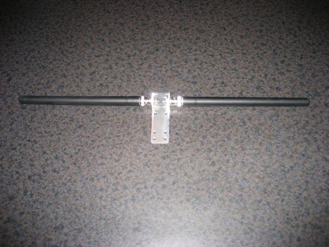
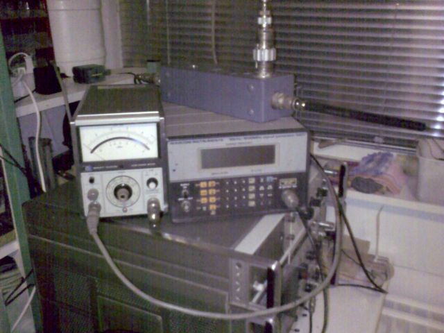
| 14-12-2009 This is how my "limited space" com antenna look like | 27-12-2009 After dusting off my RF test equipment (other hobby) The spectrumanalyzer/trackinggenerator did not work proper after a few years of non use I had to improvise, I tested the new antenna with the signal generator, power-meter and reflection bridge. The result was poor. Return loss was very bad, even with a broadband 1:1 balun. The only way to get the helical antenna working was with a proper ground plane. So that will it be in the plane, a copper grounding with the helical perpendicular on it. ( on the foto you see the antenna connected to the bridge.) |
|
|
|
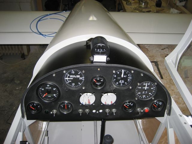
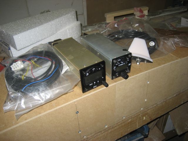
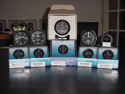
| 03-01-2008 instrument cover painted black | 03-01-2009 I bought the missing avionics! And yes! there is very few left of my end of the year bonus! |
|
|
|
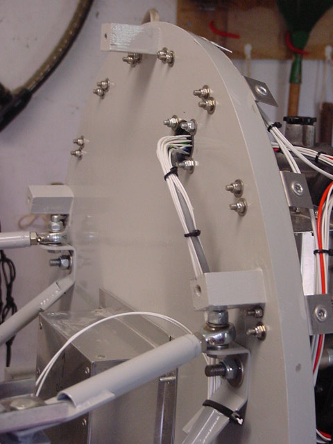
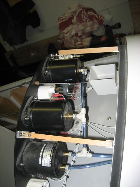
| 24-05-2006 wiring on firewall | 03-01-2008 plumbing of the flight instruments |
|
|
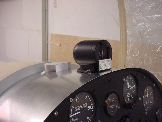
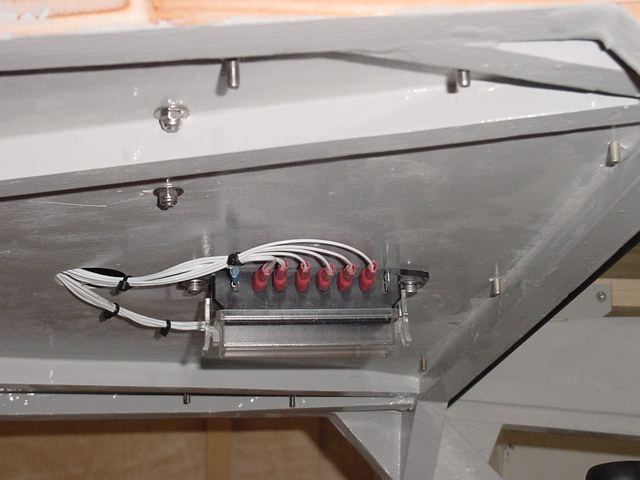
| 24-05-2006 Compass on top of panel. ventilation outlet in paper template. Now already made in alu sheet and mounted. | 24-05-2006 Fuse box below front deck. all wiring is complete! |
|
|
| 2-3-2006 First part after the skiing holliday! A combined static/pressure pitot tube. This part is going to be mount in the middle of the nosecone. using such a combined pitot tube I have only air tubing below the frontdeck. | Detail off the static slots in the outer tube. |
|
|
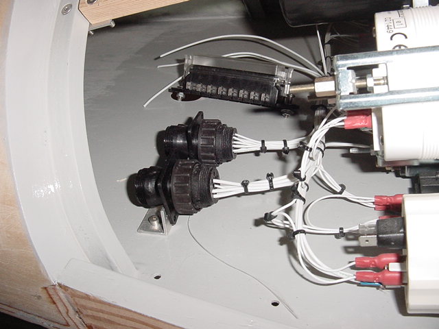
| 14-06-2005 Connector bracket on front deck. fusebox is below the frontdeck | complete view |
|
|
| There are two vacant places for COM trx and transponder. Buy these later. | PTFE wirering with AMP multipole connectors. |
|
|
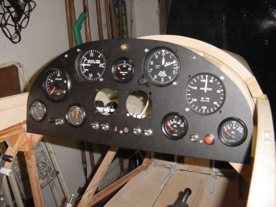
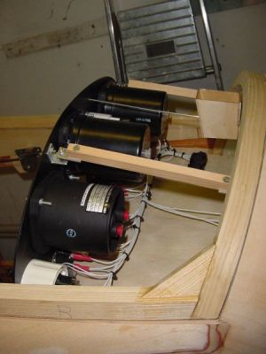
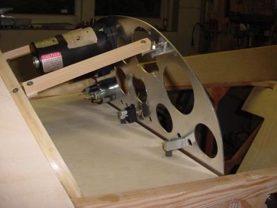
| Bought all the engine instruments at Great plains, These guys are realy cheap. Flying instruments at AS+S. Fusebox will be mounted at the back side of the panel. | The panel is fixed on rubber absorbers |
|
|
| I choose for a basic VFR instrument panel. All the instruments fit in the 2mm aluminium sheet. Also transponder and com trx are in this panel. I did not built the radio collum in the center as per plans. The panel is lasercut and powder coated. |